Apr 10, 2011, 7:41 am · #1
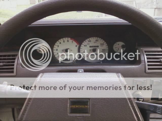
This is out of a 95-96 s14 cluster. the 97-98 have different pin placement for the speedo wiring.
Power
Power is supplied from a ignition power source. This wire needs to wired to a 7.5 amp fuse. How you do that is up to you. *Do not use the original fuse* The original fuse powers other devices.
I will be using a slot in the fuse block. There is 2 ways to do this. 1. You will need to de-pin a fuse that is not in use. or 2. Run new pins to a spare slot in the fuse block.
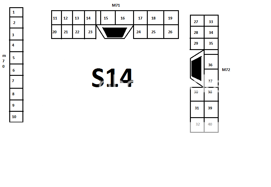
From the fuse the wire needs to be ran into pin # (14) of plug # (M71) Original wire is (G) in color. This is a common power wire that supplies power to the Tachometer, speedometer, temp gauge, and fuel gauge.
Ground
The ground is ran from pin # (40) of the M72 plug. Run a well grounded wire, black in color. This is a common ground for the speedometer, tachometer, fuel gauge, and temp gauge.
SPEEDOMETER WIRING
1st.
Speed Sensor,
Run a wire from pin # (25) of the s14's dash plug # (M71) plug to pin # (1) of the speed sensor, Original wire is (R/Y) in color.
Run a wire from pin # (26) of the s14's dash plug # (M71) plug to pin # (2) of the speed sensor, Original wire is
(R) in color.
2nd.
Variable Speed Sensor for ECU
Run a wire from pin # (18) from the plug # (M71) to pin # (24) of the dash plug # (F3). Original wire is (Y/G) in color.
TACHOMETER WIRING
Tachometer Signal to ECU
Run a wire from pin # (17) from the plug # (M71) to pin # (26) of the dash plug # (F3). Original wire is (Y/R)
FUEL GAUGE WIRING
Signal from Fuel Pump.
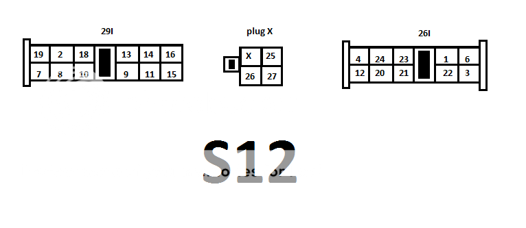
Run a wire from pin # (24) from the s14's dash plug # (M71) to The S12's dash plug # (28I) in pin location # (08), This wire is (Green/Yellow) in color.
TEMP GAUGE WIRING
Signal From Thermal transmitter
Run a wire from pin # (6) from the s14's dash plug # (M70) to the pin # (28) from the ECU plug # (F3)
And that's it for the gauges.
ILLUMINATION
Once the head light switch is turned to position 2 on the s12 this will supply power to the s14 cluster and also allow for the use of the s12's factory syle dimmer switch.
Run a wire from pin # (11) from the s12's dash plug # (29I) to pin # (32) from the s14's plug # (M72). This is the power side.
Run a wire from pin # (12) from the s12's dash plug # (26I) to pin # (31) from the s14's plug # (M72). This is the ground side.
TURN SIGNALS
LEFT
Run a wire from pin # (9) from the s12's dash plug # (29I) to pin # (21) from the s14's plug # (M71)
RIGHT
Run a wire from pin # (10) from the s12's dash plug # (29I) to pin # (23) from the s14's plug # (M71)
GROUND
Run a wire from pin # (20) from the s12's dash plug # (26I) to pin # (22) from the s14's plug # (M71)
BRIGHT BEAM signal
Run a wire from pin # (3) from the s12's dash plug # (26I) to pin # (36) from the s14's dash plug # (M72). This is the power side.
Run a wire from pin # (4) from the s12's dash plug # (26I) to pin # (22) from the s14's dash plug # (M71). This is the ground side.
BRAKE LIGHT
Run a wire from pin # (18) from the s12's dash plug # (29I) to pin # (27) from the s14's dash plug # (M72).
CHARGE LIGHT
Run a wire from pin # (20) from the s14's dash plug # (M71) to pin # (3) of the alternator
OIL LIGHT
Run a wire from pin# (4) from the s14 dash plug to the oil pressure switch.
CLOCK
Power is supplied from a ignition power source. This wire needs to wired to a 10 amp fuse. How you do that is up to you. From the fuse run the wire to pin # (1) of the s14's dash plug. It shares a common internal ground.
DOOR LIGHT
Run a wire from pin # (14) from the s12's dash plug # (26I) to pin # (08) from the s14's dash plug # (M70).
*PLUGS*