Browse › Engines ›KA24E/DE swaps

S13 KA24DE dohc to Mk1 CA20E Electrical/wiring Guide

Started by 200sxkitcar · Mar 23, 2008 · 50postsSMF 2010–26

200sxkitcarMar 23, 2008, 11:12 pm · #1

This is meant to be printer-friendly, hence the size of the pics.

Please read thru all of it ....carefully and .....slowly   before exploding with questions, thank you  

I highly recommend that you print this out and look over it that way, so you can see the pics and read it all w/o scrolling all the time  


posted image

S12 CONNECTORS-----

posted image

posted image
.......
NOTE:
posted image
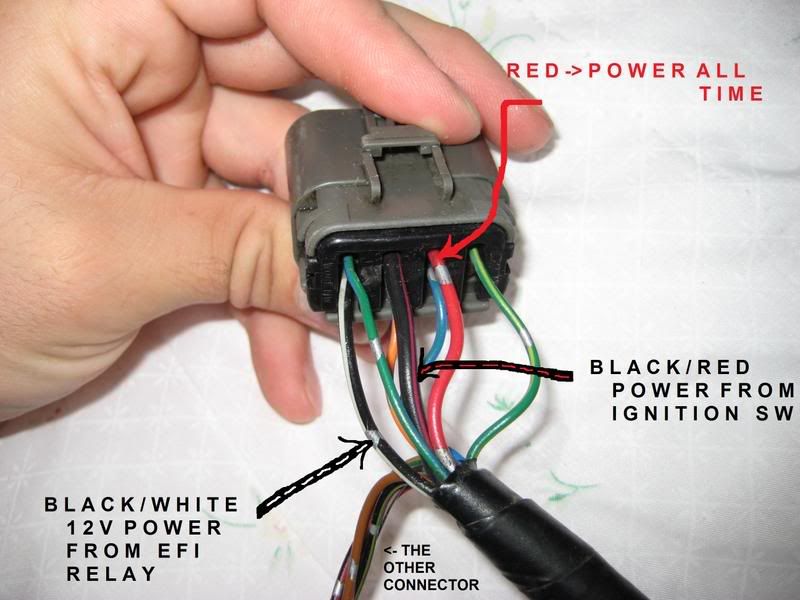
^ In this picture, you can see the coil connections (the other one is in the background slightly, look for the connector) for which you can use as a power source for the large S13 BLACK/RED wire. This is like a 12 gauge wire on the S13, so this coil wire source on the S12 will be sufficient, as its also about 12 gauge and has the same circuit function on both cars (the S13 BLACK/RED is a direct feed from the ignition switch for the coil, just like this S12 BLACK/WHITE wire).

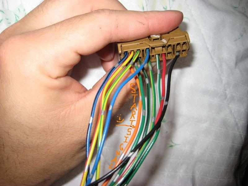
S13 CONNECTORS-----

posted image

posted image

posted image

200sxkitcarJun 16, 2008, 5:22 pm · #2

In this pic, you can see the GREEN/ORANGE wire that is the neutral safety switch wire.  Its on the seperate plugs tucked to the sides.

posted image

Other photos, for reference.  Original CA20 harness is on the right/top side, Body harness is on the left/bottom side.

posted image

You can see a hint of the GREEN/ORANGE neutral safety wire at the lower right corner of this pic.

posted image

200sxkitcarJun 16, 2008, 11:11 pm · #3

TO CONNECT UP YOUR FUEL PUMP CIRCUIT:  NOTE THIS INFORMATION IS NOT ON THE DIAGRAM ABOVE.

First off, I need to explain how the fuel pump circuit functions.  It is critical you understand this before modifying the system.

posted image

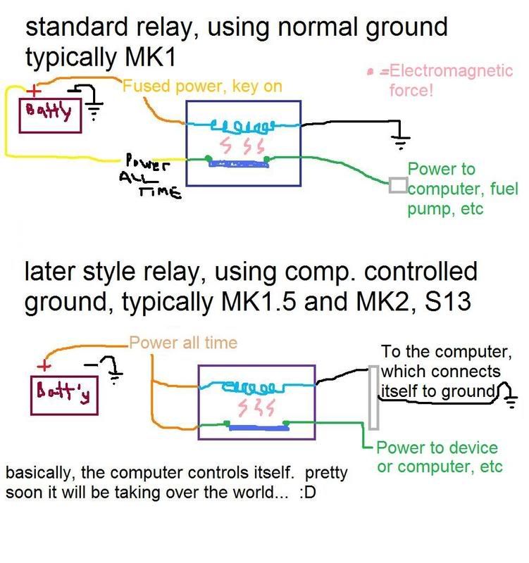
The fuel pump circuit is ground-side controlled.  What this means is that power is supplied to the fuel pump, and either the computer-- or the fuel pump relay-- controls the ground, and therefore whether the pump runs or not.

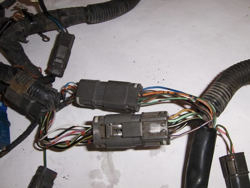
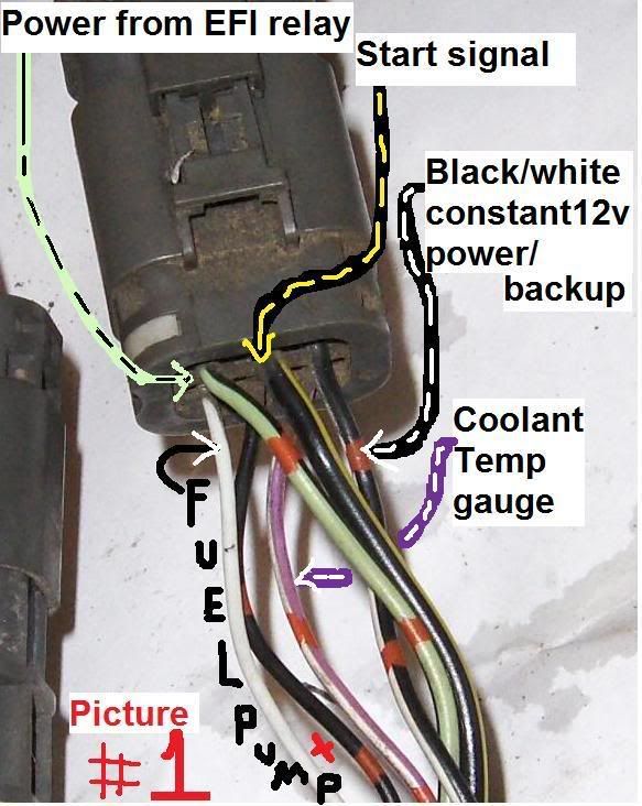
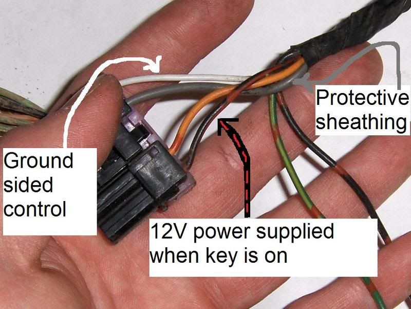
So in the S12, when the key is turned to the ON position, 12V power is supplied through the fuse block back to the fuel pump through a BLACK/RED wire.  On the ground side of the fuel pump, a black or white wire exists (depending on when your car was built, how stoned the guy was building the loom, the position of Neptune, who the fuck knows).  This black wire or white wire runs through one of the connectors in the engine bay (PICTURE #1), back up to the computer, and then the computer grounds the wire as it sees fit, turning the pump on or off (or somewhere in between, actually).
posted image

The other wire that you see, the one that's located in the middle of the connector, is the shielding wire.  When current flows through a wire, it creates a magnetic field, which can disturb the flow of electricity in other wires that are near it.  So Nissan took bare metal (in this case, aluminum) and ran a stranded cover overtop the rubber insulation of the fuel pump wires.

posted image

When it gets to connectors, though, the metal covering has to split off, so they put it through an extra pin in the connector.  This covering is normally grounded at one end, in the case of the S12, it is normally grounded through the CA20 EFI harness on the engine somewhere, which you just removed.  So what I do is either splice in a wire to that black-with-red-dots wire in PICTURE #1 and connect the longer wire to ground, or just connect that original one directly to ground with a screw, its whatever you like.

end of lesson.

--------------------------------------

SOââ,¬Â¦

For the fuel pump control, there are several options.

IF you are using the stock pump,

1.  You can directly hard-wire the pump to ground which means that it will run all the time when the key is on.  Normally the pump is controlled by the ECU, either directly or through a relay, and will only run for a few seconds before and after startup.  If you hardwire the pump direct, you will bypass this function.  Benefits are simpler wiring; drawbacks are potential hazard in an accident (normally if the engine would stop running, then so will the fuel pump).  That decision is yours to make.

There are several ways to hardwire the pump directly, you can choose to ground it out either somewhere near the rear of the car- by the pump, by the connector- or you can ground it out in the engine bay where the EFI connectors are at.  Again, this is preference.  As long as you are modifying the wires up front, I'd rather do it there, as its less work and less chance of a spark near the rear of the car if things came undone.

If you decide to ground the wire at the connector in the engine bay, you will need to ground the wire that is located on the outside corner of the connector.  I have run into different situations as to what color this wire is, IN this picture it is represented by the WHITE wire in PICTURE #1.  You simply ground this wire to a good, clean, secure ground.

posted image

If you decide to ground the wire in the rear of the car, you will need to look at the fuel pump connector.  The wire you are after is located on the *OPPOSITE* end of the connector with the BLACK/RED wire.  See picture.
posted image

Sometimes this wire is black, sometimes its white.  It should match whichever color the wire is up front in the engine compartment as shown in PICTURE #1.  Ground this wire, and then the pump will run all the time when the key is on.
...........

2.  You can add in a relay control.  Since the computer we are using here is an S13, you can take a look at the lower diagram.  
posted image

^The lower diagram is the system that needs to be set up.

posted image

What can be done is this.  Take the WHITE -or- BLACK wire,(... depending on which you have, in PICTURE #1 on the outside corner of the connector...,) that is going to serve as the one of the Switched leads.  Connect the other switched side to a GROUND of your choice, however you want to do that.    

For the Control side of the circuit, tap the constant 12V BLACK/WHITE wire in the S12 Connector in Pic#1 and connect it to one of the control side leads.  Now take the other control side of your relay and connect it to the S13 BLACK/PINK wire.

JUST MAKE SURE that you do NOT send the solid 12V to the BLACK/PINK wire.  This will damage the ECU.  The BLACK/PINK wire MUST be connected to the control side of the relay ONLY.

-----------------------------

IF you are using an aftermarket fuel pump, like the high-flow Walbros, you're going to need to run a larger power supply wire than the factory one.  Once that is done, you can connect in a relay in similar fashion, its just the setup of the wires that will be different.

You are adding the NEW RED wire.  It could be blue, green, pink, whatever.  I used RED for this example.

posted image

What is necessary here is changing the arrangement of the wires at the fuel pump connector.  You will need to cut the WHITE wire (or BLACK wire depending on your setup) from the connector, because that is going to be the relay control circuit, and you don't want a full 12 volts going thru back to the computer as I mentioned before.  That WHITE (or BLACK) wire, the section that is left connected to the actual pump CAGE/SENDING UNIT, needs to be connected to ground now, wherever you decide is a good clean place to ground to.  The other section of the white wire, which goes to the front of the car and is now not connected to anything, is going to get connected to the relay and serve as the control side of the relay.

posted image

A closer shot,

posted image

NOW for the BLACK/RED wire, you are going to be extending the Connector end of your cut wire to the relay, where the relay when activated will provide 12V to the fuel pump itself.  

THE OTHER END of the BLACK/RED wire, the chassis side of your cut, just needs to get capped off.  Do this well otherwise you'll be blowing fuses, etc, if it shorts to ground, because that circuit will still be sending power thru that wire.  I don't think you can just pull the fuse, as that same BLACK/RED wire also sends power to the ECU.  You could use to power something else back there I suppose, but the OEM pump only pulled 2amps down that circuit, so it better be pretty light if you do add anything.

NOW for the OTHER end of the chassis white wire, up front in the connector in PICTURE #1, you will connect this to the S13 BLACK/PINK wire.  Again, this is happening at the front of the car, in the engine bay.

200sxkitcarJul 24, 2008, 3:35 am · #4

I think, finally....

this is done.

I realize that this forum is nearly all male, and its possible that some of us may be colorblind to some extent, so if you have a hard time with any of these posts colorwise let me know and I'll make some adjustments for ya.

Any questions feel free to ask, but this is a rather complex string of information,

so I ask that you please,

read
,

thru it carefully,

and slowly,

a few times,

before posting up a bunch of questions.

As always, if you are deeply confused, or just want to affirm everything, you can PM me or call me, whatever works best for you.

Thanks!

200sxkitcarJan 24, 2009, 4:18 am · #5

Corrected the error in the fuel pump wiring.  see option 2 diagram for changes.

myth_S12Jan 27, 2009, 7:30 pm · #6

i'm guessing on the Tan S13 wiring connector from the ECU (3rd picture for the S13 wiring), Pin's 1 & 2 are the Tachometer Signal (yellow.red) and Coolant Temp Sensors (blue.black)?

thanks.

200sxkitcarJan 28, 2009, 12:23 am · #7

as far as I am aware, yes.  I do not have confromation of this tho, so please verify and let me know!  The rest of it is solid, I used it for wiring Henry's KA, but he had a separate temp sensor and the digi cluster was no good, so dunno about how that would work out.  is yours digi or analog?

myth_S12Jan 30, 2009, 5:45 pm · #8

Ok, yeah. this wiring guide is straight forward. thanks.
my cluster is analog.

200sxkitcarFeb 3, 2009, 2:39 am · #9

cool.  please do post up if you get the gauges to work...

myth_S12Feb 3, 2009, 8:05 pm · #10

quick question.
Where are these S12 connectors located?
I see all the S13 connectors on the harness?

ehh..

David BFeb 4, 2009, 1:23 am · #11
myth_S12
quick question.
Where are these S12 connectors located?
I see all the S13 connectors on the harness?

ehh..
'
what he said! im so ,losty on that. where IS picture numebr one s12 connecter located?

edit,

nevermind sterling said there under where the stock airbox is in another thread
silvia loveFeb 4, 2009, 1:24 am · #12
David B
'
what he said! im so ,losty on that. where IS picture numebr one s12 connecter located?

edit,
nevermind sterling said there under where the stock airbox is in another thread
its hiding right under your maf/airbox.
tweaker_s12Feb 15, 2009, 9:31 pm · #13

sterling i need you explain, what is up with the blue & white coil wire. i thought that the ecu handled the coil stuff. i printed this off and this is the only i dont get thanks

silvia loveFeb 15, 2009, 11:23 pm · #14
tweaker_s12
sterling i need you explain, what is up with the blue & white coil wire. i thought that the ecu handled the coil stuff. i printed this off and this is the only i dont get thanks
the ca20e coil gets power from that blue/white wire, which is thru the chassis harness. it only sends 12v when the key is on on/start.
the ka only needs power to the computer, which then splits it to various things. the coil for the ka's plugs directly to the engine harness, being powered when the computer gets powered. so the ka ecu powers the coil when the ecu itself gets turned on. when swapping to a ka we use the blue/white wire to power our computer, not coil.
tweaker_s12Feb 15, 2009, 11:45 pm · #15

i get it thanks

David BFeb 16, 2009, 1:36 am · #16

which one is primary coil, i have the one thats across from the exuast manifold hooked up to the ecu

not the one under the airbox right?

200sxkitcarFeb 17, 2009, 12:38 am · #17

I don't know exactly what you are asking, but the S12 COIL POWER WIRE IS ONLY FOR 12V POWER FOR THE S13 ECU.  IT IS NOT TO PROVIDE COIL AND SPARK FOR THE KA DISTRIBUTOR.  just as long as we are clear.  You need to use the S13 coil, which connects to the S13 harness.

Whichever BLACK/WHITE wire you choose to use, whether its the primary (intake) or secondary (exhaust) coil 12v power supply wire, doesn't matter as it is 12V constant power when the key is on, regardless.  They are the same circuit.  There is only one BLACK/WHITE wire there, it just has a splice with two ends, one at each s12 coil.

So basically you could use either one, whichever is more convenient.

---------------------------------

a correction for the above comments:

THE BLUE and BLUE/WHITE wires ARE S12 ECU CONTROL WIRES.  They do not have any voltage going to them, or going out of them, when the CA20 ECU is removed.  When you put a KA in, these wires become useless.

Edited for correction:

the ca20e coil gets power from that BLACK/WHITE wire, which is thru the chassis harness. it only sends 12v when the key is on on/start.
the ka only needs power to the computer, which then splits it to various things. the coil for the ka's plugs directly to the engine harness, being powered when the computer gets powered. so the ka ecu powers the coil when the ecu itself gets turned on. when swapping to a ka we use the S12 BLACK/WHITE wire to power our computer, not coil.
tweaker_s12Feb 22, 2009, 1:46 am · #18

you have a black/yellow for the air reg. and then a black/yellow for the fuel pump. can you tell me what is up with this.  thank you

EDIT: im just talking about the s13 harness, to clarify

s12godFeb 22, 2009, 3:23 am · #19

Is this the same for ca18et cars?

200sxkitcarFeb 22, 2009, 10:29 pm · #20

it is not quite the same for the ca18et cars, I need to do a separate writeup for those, as the s12 connectors are different, but the setup is similar.

--------------------------
IN AN S13, the BLACK/YELLOW wire feeds BOTH the air regulator and the fuel pump, actually, they just 'T' the fuel pump wire and feed it to the air regulator.  why this is done this way is beyond me, but thats how it is shown on the s13 diagrams.

I'm not quite sure where you grabbed that info from, hope this helps, ask more if necessary....

tweaker_s12Mar 1, 2009, 2:30 am · #21

when you wired up arro's car, you just run the wires from the s13 harness, where the battier is, across to where the s12 harness is under the air box right? that it right? I'm thinking that you have to hook up relays for the efi and wire up a fuse block. now I'm thinking that i just i need to run the wires to the s12 harness and then the relay that are on the s12 harness will do all the work and the s12 fuse block. if i just splice the s13 harness into the s12 harness like you have stated i will be OK right?

ps: i im so lost in the sauce

David BMar 14, 2009, 8:26 am · #22

you run the wires from the batt side where the S13 connectors end up across the bay to the airbox side where the stock S12 connectors are at.  its like a 4foot jumper harness, basically.

other than a fuel pump relay if you so desire there are no additional relays that need to be added.

posted image

yea i made a jumper harness on my SOHC

just buy those multi color electrical tape from walmart, and just like tape white, to white, on each end,

so when you bunch the wires together, you can remember which one is which

unless you go buy multi colred wire... which is a pain

200sxkitcarMar 16, 2009, 1:54 am · #23

No prob.  An alternative to what David said with the tape is to purchase 4-flat trailer wiring, which gives you four wires bundled together.  I ran two sets of this on Arro's car, and put tape on one set to designate which was which.

BTW, four flat wire has white, green, brown, and yellow wires all grouped together:
posted image

Ususally 14 gauge or so.

I built his harness using the 4-flat wire with ends on it, and made everything plug&play so it could be modded easily.
posted image

JayMay 17, 2009, 8:58 pm · #24

Another Thing to add to this list. When the Yellow/Red wire DOESN'T work for your factory tach. splicing it in RIGHT after the coil on the KA24DE's on the Green/Black Wire. You oly have about 3 inches of wire. Splice it in there before it goes into a little black box, and that will be right as rain for your tach.
-J

DatsmOJul 22, 2009, 6:57 pm · #25

where does the red w/ black stripe connect to on s12? there is no mention of it on the color chart. its the fifth picture down with the brown connector for the efi control.
posted image

200sxkitcarJul 23, 2009, 1:22 am · #26

for a mk1 s12, its not needed, as the chassis controls the EFI relay, not the computer.

That is a multi-purpose pic for other writeups (ie mk2->ka thread) hence extra labeling.

schassisownerAug 26, 2009, 9:54 pm · #27
200sxkitcarfor a mk1 s12, its not needed, as the chassis controls the EFI relay, not the computer.

That is a multi-purpose pic for other writeups (ie mk2->ka thread) hence extra labeling.


alright i got a few questions as im sorta a noob with wiring.

since the s12 and s13 have the plugs on different sides, couldnt you move the plugs from the DS to the pass side on the main harness?

it would eliminate the excess wiring by not having to route it from the pass side to the drivers side; and the wires that run to the relays on that side could be cut/ and wire could be resodered to make the harness longer to the relays

i know its alot of work but if you use the same gauge wire is there any harm in doing this?

also as stated deleting these plugs (from S13 to s12) and sodering the connections according the the diagram

i did read this is merely a suggestion so to make the harness look alot cleaner
kyskaterAug 27, 2009, 7:32 am · #28

what i did was run the s13 harness that you splice into uned the center console and ran them where the factory wiring passes through on the ds under dash area. i did this after i hatted th look of the sloppy jumper between the front rails..

VG30_S12Sep 24, 2010, 9:13 am · #29

ok i gonna ask, can someone post pics of the engine bay and of the wires and what they did? im more of a visual learner... ive read through several times and cant get it down :(

ArroSep 24, 2010, 12:42 pm · #30

There are very few wires but if I get a chance I will try today.

mrjacobwhoNov 2, 2010, 10:56 am · #31

I finally get it! Hah Thanks!! Theres just one thing, I chose to ground my fuel pump under the hood, but when I looked, the fuel pump wire runs out and away from the plug, connects with the wire next to it, and continues as one. So, if I continue and ground the wire, I would be grounding the both of them. I dont want to ground something that doesnt wanna be. Haha Any suggestions?

Thanks again, Jake

200sxkitcarNov 17, 2010, 11:48 pm · #32

The other wire is just for electrical shielding, you can ground it at the same place.

ka-tgazelleJan 24, 2011, 9:18 pm · #33

Not to bring back an old thread but whats the cold start wire?  I used your write up for the ca-vg and cross referenced the wiring , because I pulled my vg after tranny blew and now it has a ka-t in it and I need to finish the wiring (which is what 7 wires).  So Im doing to write because I think I got it right and want to know if Im correct. So if you could Im gonna pm you a link to the thread once I'm done.

slideurmomFeb 5, 2011, 12:19 pm · #34

so do i keep the harness on the driver side or do i dump it .im so lost lol and can u post pics of where u can find these plugs that u have to splice. thanks

MaxpowFeb 25, 2011, 8:28 pm · #35

I just don't get what the heck I am supposed to do for this. Can someone call me and walk me through or give me a post on this thread that says step by step what the hell we are splicing and what we need as far as materials. Sterling is out of town and I am fucked on this parts order if I don't finish soon.

slideurmomMar 10, 2011, 1:52 pm · #36

^yes peas ... this is the only thing thats holding me back

ka-tgazelleMar 10, 2011, 2:35 pm · #37

I just wired a switch connected to the fuel pump ground to turn it on. I think this is ok i know in an accident it wont shut off but i dont plan on crashing.

David BMar 10, 2011, 2:50 pm · #38
ka-tgazelle on 02:35:14 PM / 10-Mar-11I just wired a switch connected to the fuel pump ground to turn it on. I think this is ok i know in an accident it wont shut off but i dont plan on crashing.

any key ignition source will work.. even where the stock ig coil is, or even on the fusebox (use a fuse tap) bottom left on the interior fusebox, is like engine control fuse, which isnt really used anymore.


Post Merge: [time]08:52:21 PM / 10-Mar-11 [/time]
slideurmom on 01:52:43 PM / 10-Mar-11^yes peas ... this is the only thing thats holding me back

go LOOK, under where the stock s12 airbox is!! the s12 connecters are posted. grab some cleaner, wipe off the dirt from the wires, and locate the simliar plugs posted under S12 PLUGS, and make sure the wires sort of match up!

REMOVE the S12 engine harness, which comes from under the drivers side fender, or just cut if if you dont want to pull the fender.

do NOT remove the s12 chassis harness AKA harness on each sides of the bay, that are connected to RELAYS and such,

but REMEBER, the stock s12 ignition coil wire carry 12 volt power when the key ignition is on! so use that wire for power to a source, or tape it up so it doesnt ground out!
slideurmomMar 11, 2011, 12:36 pm · #39
David B on 02:50:01 PM / 10-Mar-11any key ignition source will work.. even where the stock ig coil is, or even on the fusebox (use a fuse tap) bottom left on the interior fusebox, is like engine control fuse, which isnt really used anymore.


Post Merge: [time]08:52:21 PM / 10-Mar-11 [/time]
go LOOK, under where the stock s12 airbox is!! the s12 connecters are posted. grab some cleaner, wipe off the dirt from the wires, and locate the simliar plugs posted under S12 PLUGS, and make sure the wires sort of match up!

REMOVE the S12 engine harness, which comes from under the drivers side fender, or just cut if if you dont want to pull the fender.

do NOT remove the s12 chassis harness AKA harness on each sides of the bay, that are connected to RELAYS and such,

but REMEBER, the stock s12 ignition coil wire carry 12 volt power when the key ignition is on! so use that wire for power to a source, or tape it up so it doesnt ground out!

my plugs and wires look different from the ones in the picture .ive looked like a hundred times ,srry for being a noob .
ka-tgazelleMar 12, 2011, 12:44 am · #40

I was wondering if any could help me finish  figuring out the wiring for my vg to ka-t. I have the car running but the engines only running using 4 wires which i know it runs on more. if some one could help me please I would very much appreciate it. I cant find out what wires are needed to run the ka properly. Yes my car starts but runs really rich right now. I need to figure out the rest of the wiring but no one has really looked in to it like me. So I cant find anyone to help with a second opinion.

JayMar 12, 2011, 3:36 am · #41

You only need 4.

Power to ECU constant
Power to ECU ignition
Ground
Starter signal.

Everything else needed it just gauges and fuel (If you choose to wire in a relay for it)

I have have everything wired up on two 4 pin trailer wiring plugs. One's for power and ground, one's for gauges. I have 8 wires total.

slideurmomApr 15, 2011, 12:01 am · #42

^can you take a pic of your setup .thanks

freestyle mindedSep 24, 2011, 7:53 pm · #43

has any body tried to get their s12 BAR'd... thats wat i want to do, so if i need to run more wires for some other smog..r u guys running egr or charcoal canistor,, ?

i hope this isnt off topic

by the way awesome thread

JaySep 24, 2011, 7:55 pm · #44

You shouldn't need to run any more wires for smog. All that is handled on the engine harness from the ECU anyway.
Would just be a matter of installing the needed hardware.

freestyle mindedSep 24, 2011, 9:01 pm · #45

very true thanks

ArroSep 24, 2011, 10:01 pm · #46

Isnt the EGR vacuum controlled based on throttle?

freestyle mindedSep 26, 2011, 12:17 am · #47

yea i forgot think basics, its a vacuum style egr system,
ima post a thread n see if anyone has been able to B.A.R. there ka swap

S12PreludeDec 30, 2011, 10:24 pm · #48

I have an mk 1.5 Silvertop, b trans. Is the wiring the same?

Dr.SteelsApr 15, 2012, 3:59 pm · #49
Jay on 03:36:52 AM / 12-Mar-11You only need 4.

Power to ECU constant
Power to ECU ignition
Ground
Starter signal.

Everything else needed it just gauges and fuel (If you choose to wire in a relay for it)

I have have everything wired up on two 4 pin trailer wiring plugs. One's for power and ground, one's for gauges. I have 8 wires total.
so jump:
black/white to red for Constant ECU power
Black/white at the coil
ground? (I see no reference as to where this wire is located on any of the plugs)
black/yellow to orange

Is the above correct? Does everything else just plug into each other?

If i wish to make the guages work I would do the following?

1.purple/white to blue/black for CTS
2.blue/white to yellow/red for tacho

If number two does not work then:

blue/white to green/back

Any corrections in this?
superDoriftoJun 13, 2013, 11:16 am · #50

So legitimate question before I start tearing into the wiring diagram...

is everyone just taping into the power supply as noted in the pics on the body harness plugs and leaving the old CA efi harness tucked neatly out of the way?  Or is it possible to remove to the entire CA EFI harness, make the nessecary jumper connections to the body harness and call it a day.

I would much prefer to remove the old harness completely and do a bit of a tuck, but I did not see any mention of removing the old harness.  My main conern is that ther eare important grounds that are in that harness that would need to be retained to keep the body harness funcitonal?

sent out a few PMs to the author, but not sure if he frequents the boards anymore.